Overview
Wall Thickness Analysis
Wall thickness refers to the distance between one surface of the model and its opposite sheer surface. Wall thickness is defined as the minimum thickness that the model should have at any time. Every surface of the 3D model must be assigned a wall thickness. With the help of a CT 3D scanner and 3D inspection software, wall thickness analysis can be calculated on mesh and volume objects using both ray firing and sphere growing methods. Like a nominal 3D CAD actual comparison, a wall thickness analysis is typically displayed as a color map on the surface of the part. It is then possible to see at any point what the calculated wall thickness is in that area. Discrete points can be selected and the wall thickness measurement can be reported. This is possible in both 3D and 2D. The output report includes Wall Thickness Analysis, four ranges of critical thickness, faces, the amount of surface area, and the percentage of analyzed area that fall into those ranges, and all Critical features in the desirable CAD format.
WORKFLOW
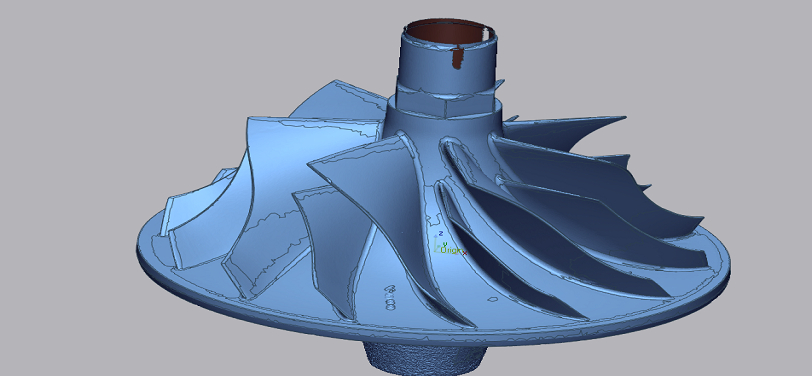
 Import cad file (8).png)
Import CAD file
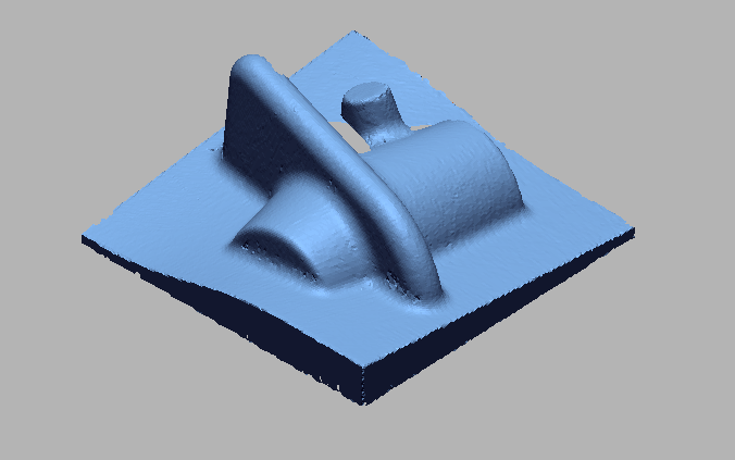
 import 3d scan file (10).png)
Import 3D scan file
 datum allignment.png)
Datum Allignment
 Select thickness to measure wall thisckness.png)
Select thickness to measure wall thisckness
 wall Thickness.png)
Wall Thickness
 wall thickness dimensions.png)
Wall thickness dimensions
VIDEO
INDUSTRIES WE SERVE
WHAT'S NEXT?


RELATED BLOGS
Scan To Parametric CAD
Parametric cad consists of a history-based feature modeling tree that can be edited to make design
Read more
Scan To Parametric CAD
Parametric cad consists of a history-based feature modeling tree that can be edited to make design
Read more
Scan To Parametric CAD
Parametric cad consists of a history-based feature modeling tree that can be edited to make design
Read more