VEHICLE CAD REVERSE


BIW (Body In White) to Scan CAD is a key for design study, crash analysis new product development case study & stimulaization etc....

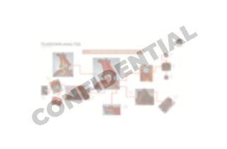
PROCESS AND METHODOLOGY

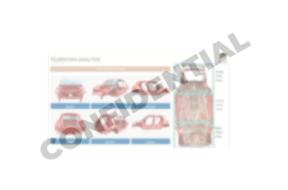
IMPORT ASSEMBLY 3D SCAN FILES

  • Using GOM blue light scanner for scanning the entire BIW Web
  • Importing assembly scan data in .stl format
vechicle-cad-reverse-3d
vechicle-cad-reverse-3d-import

CREATING COORDINATE SYSTEM

  • Creating coordinate system based on BIW Profile & Feature
vechicle-cad-reverse
vechicle-cad-reverse-coordinate-system

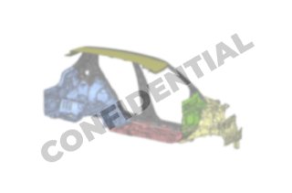
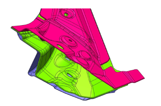
CREATING CAD FOR ASSEMBLY
SCAN DATA

  • Develop outer skin design of the entire BIW assembly from the scan data
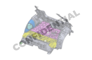
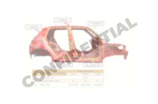
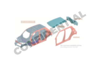
vechicle-cad-reverse-assembly
cad-creation

BIW TEARDOWN

  • Our experts will do physical teardown of BIW for separating panels & parts based on the subsystem.
teardown
vechicle-cad-reverse-teardown

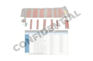
IMPORTING INDIVIUAL PART SCAN DATA

  • Using GOM blue light scanner to scan the individual parts.
  • Importing & aligning individual panels & parts scan data to the assembled scan data based on profiles and features
vechicle-cad-reverse-importing-parts
part-scan-data

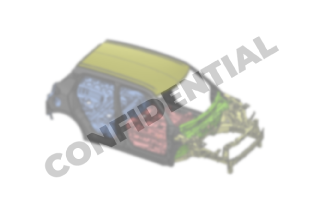
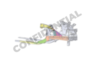
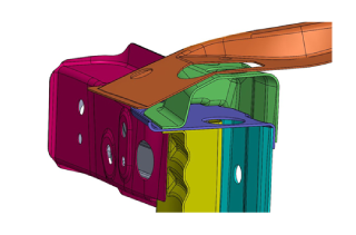
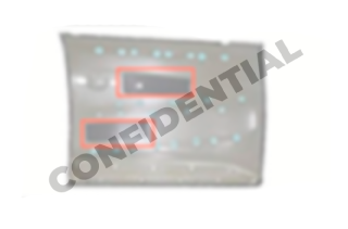
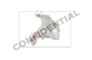
CREATING CAD OF INDVIUAL PANELS & PARTS

  • Developing design of individual part features and profiles based on the scan data.
vechicle-cad-reverse-indviual-parts
vechicle-cad-reverse-3d-scan-developing-design

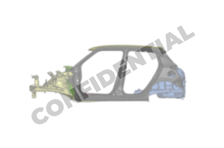
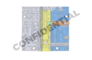
INTERFEREANCE ANALYSIS

  • Interference and mating surface analysis on assembled CAD data.
vechicle-cad-reverse
interference-vechicle-cad-reverse-3d-scan-analysis

ACCURACY ANALYSIS

  • Ensure the perfect surface of BIW scan data to CAD data
vechicle-cad-reverse-accuracy
perfect-cad-data

EXPORT CAD DATA

  • Export either as individual file or assembly file based on customer requirements.
export-data
export-data-vechicle-cad-reverse-3d-scan

DELIVERABLES

Design data - .STEP , .IGES , .X_T & SAT, etc

Scan data - .STL

Teardown reports

  • Teardown photography . JPEG
  • BOM - excel
  • spot welled, hole plug, sealant, stud, etc... in PPT
  • FREQUENTLY ASKED QUESTIONS

    Cinverting complete vehicle Scan to CAD format ,which is a key for design study, crash analysis, new product development case study & stimulaization etc.

    The Xaxis points forward from the vehicle. The Yaxis points to the left, as viewed when facing forward. The Z axis points up from the ground to maintain the right-handed coordinate system.

    Overall accuracy of about.1 mm between the parts could be maintained.

    Design data - .STEP , .IGES , .X_T & SAT, etc