Overview
3D Scan alignments for CAD / CAM /CAE
Normally, the CAD part we import in the reverse engineering software does not have coordinate points initially, and they are called hanging coordinates. The purpose of digital alignment is to position the part, arrest the coordinates (0,0,0) points during any manufacturing or machining process so that the parts won’t move and be completely locked in a position. In Geomagic Design X, a feature called Align wizard is present, and it has different alignment modes. The first one is regional alignment in which regions are created in the geometrical features and positioning is made using the X and Y vector. This is also called segment alignment. The second method is Interactive alignment, which is a profile based sketch alignment. The hanging coordinates will automatically be fixed to (0,0,0) based on the sketch entities and if we move to any point in the plane, it will be fixed at the origin point only.
WORKFLOW
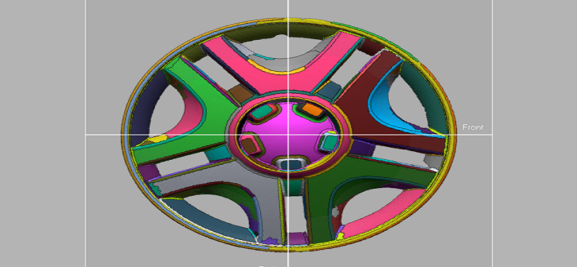
 Import un Aligned mesh file.png)
Import un Aligned mesh file
 Segmenting Feature regions on mesh.png)
Segmenting Feature regions on mesh
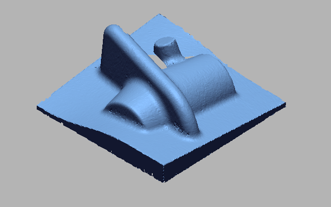
 Creating Reference Geometries.png)
Creating Reference Geometries
 Alignment based on reference planes and vectors.png)
Alignment based on reference planes and vectors
 Fully Aligned data.png)
Fully Aligned data
IMAGE
VIDEO
INDUSTRIES WE SERVE
WHAT'S NEXT?


RELATED BLOGS
Scan To Parametric CAD
Parametric cad consists of a history-based feature modeling tree that can be edited to make design
Read more
Scan To Parametric CAD
Parametric cad consists of a history-based feature modeling tree that can be edited to make design
Read more
Scan To Parametric CAD
Parametric cad consists of a history-based feature modeling tree that can be edited to make design
Read more