Overview
Engineering Drawing
An engineering drawing is a type of technical drawing used to define the requirements for engineering products or components. It describes the process of making the item, used to convey engineering ideas during the design process, or provides a record of an existing item. 2D engineering drawing is still largely used for the production of schematics. MEP Drawings are shop drawings that are a method used for the installation of mechanical, electrical, and plumbing building services. These drawings are developed in 3D using Building Information Modelling. The models are delivered to the customer as an IGES and STEP file.
Engineering Drawing to 3D Conversion
Engineering drawing to 3D CAD conversion is the process of converting 2D Technical drawings into 3D CAD Models. 2D drawings are in the x and y-axis where a 3D CAD Model has the additional z-axis. First, input 2D drawings are studied along with tooling capacity. Our team began the development of 3D CAD models based on the 2D files step by step using reverse engineering software. Final assembly model, fabrication drawings along with BOMs, and exploded isometric views of the assembly were shared with the customer. Comprehensive 3D CAD models with all detailed information help the customer in a better manner with reduced turnaround time. The CAD conversion establishes a digital platform for all the designs to facilitate design changes in the future.
WORKFLOW
PHASE 1
 Read Drawing Completely and get idea of modeling.png)
Read Drawing Completely and get idea of modeling
 Start with main body sketch.png)
Start with main body sketch
 Revolve the sketch to get partial Body.png)
Revolve the sketch to get partial Body
 Sketch other feature dimensions.png)
Sketch other feature dimensions
 Revolve or Extrude other Features need to add.png)
Revolve or Extrude other Features need to add
 Trim surfaces or Boolean Solid to get Main body.png)
Trim surfaces or Boolean Solid to get Main body
 Adding thickness to surface if made with surface.png)
Adding thickness to surface if made with surface
 Sketch additional features with specified dimensions.png)
Sketch additional features with specified dimensions
 Sketch additional features with specified dimensions.png)
Sketch additional features with specified dimensions
 Extrude that sketch to get Inside profiles.png)
Extrude that sketch to get Inside profiles
 Revolve that sketch to get Additional profiles.png)
Revolve that sketch to get Additional profiles
 Adding Holes with Specified Dimensions.png)
Adding Holes with Specified Dimensions
 Pattern and Mirror the hole wherever Required.png)
Pattern and Mirror the hole wherever Required
 Adding Fillets to the Sharp edges.png)
Adding Fillets to the Sharp edges
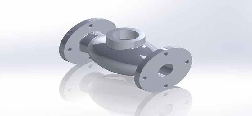
 Final Model.png)
Final Model
 Final Model in wire frame.png)
Final Model in wire frame
 Final Model in cross section.png)
Final Model in cross section
IMAGE
VIDEO
INDUSTRIES WE SERVE
WHAT'S NEXT?


RELATED BLOGS
Scan To Parametric CAD
Parametric cad consists of a history-based feature modeling tree that can be edited to make design
Read more
Scan To Parametric CAD
Parametric cad consists of a history-based feature modeling tree that can be edited to make design
Read more
Scan To Parametric CAD
Parametric cad consists of a history-based feature modeling tree that can be edited to make design
Read more