Overview
Boundary comparison
In 3D CAD models, explicit geometry constraints combine with auxiliary shape elements to form solid boundaries and participate in 2D and 3D sketches. The Boundary feature in 3D inspection software creates NURBS surfaces inside of patch boundaries using an algorithm based on the mesh. The boundaries are created by a 3D patch network by the end-user. Boundary comparison requires clean optimized mesh and can work on complex organic geometries. The initial step is to import the 3D scan data and CAD data into the 3D inspection software and align them. We can use RPS(Reference Point System) alignment to create a coordinate system of the actual data and align it to the nominal coordinate system. We can use the 3D compare feature for color mapping. Geometric features like boundary deviation can be used to compare the local mapping boundaries and pattern boundaries of CAD data. The output report is generated in the Customer's desirable format.
WORKFLOW
 Import Cad File (6).png)
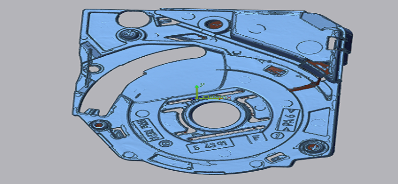
Import CAD File
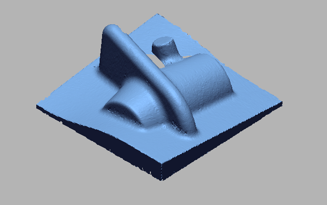
 Import 3D scan File (7).png)
Import 3D scan File
 Initial alignment (3).png)
Initial Alignment
 Bestfit alignment (2).png)
Bestfit Alignment
 Boundary comparison.png)
Boundary Comparison
 boundary comparison tabular column.png)
Boundary Comparison Tabular Column
 Boundary comparison.png)
Boundary Comparison
VIDEO
INDUSTRIES WE SERVE
WHAT'S NEXT?


RELATED BLOGS
Scan To Parametric CAD
Parametric cad consists of a history-based feature modeling tree that can be edited to make design
Read more
Scan To Parametric CAD
Parametric cad consists of a history-based feature modeling tree that can be edited to make design
Read more
Scan To Parametric CAD
Parametric cad consists of a history-based feature modeling tree that can be edited to make design
Read more