Overview
Airfoil Twist Analysis
Turbine engines have hundreds of airfoils, consisting of complex arrays, and are inspected at an average of one airfoil an hour using a conventional Coordinate Measuring Machine (CMM).Utilizing a Handheld 3D scanner and a 3D inspection software creates an associated mesh that can be compared to nominal CAD for critical feature deviation and reported within minutes. A simple surface deviation color map can indicate quick imperfections from the trailing edge of an airfoil. Initially, 3D scan data and CAD data are imported into 3D inspection software. Alignment is made and choose the 3D compare feature for base plane and uses Airfoil feature for adjusting color map and coordinate system. Again we need to select the 2D twist feature for analyzing the blade portion with primary and secondary constraints. A custom report can be created to provide an automated reporting workflow with desired CAD output.
WORKFLOW
 Import Cad file (5).png)
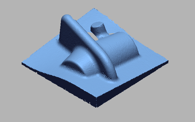
Import CAD file
 Import 3D Scan File (6).png)
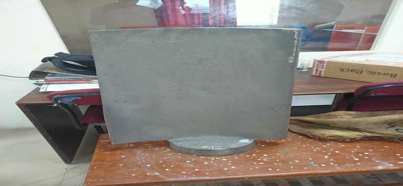
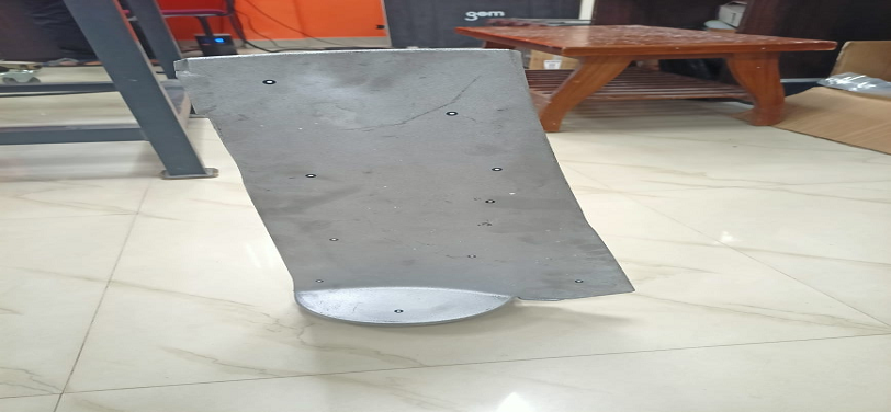
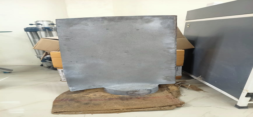
Import 3D Scan File
 Doing initial Allignment for alligning cad wit Scan data (1).png)
Doing initial Allignment for alligning CAD with Scan data
 Doing Best Fit Allignment for precise allignment (1).png)
Doing Best Fit Allignment for precise allignment
 Taking Cross Section for Airfoil Twist Analysis.png)
Taking Cross Section for Airfoil Twist Analysis
 Applying tollerance.png)
Applying tollerance
 Airfoil Twist Analysis.png)
Airfoil Twist Analysis
 Airfoil Twist Analysis measurement.png)
Airfoil Twist Analysis measurement
VIDEO
INDUSTRIES WE SERVE
WHAT'S NEXT?


RELATED BLOGS
Scan To Parametric CAD
Parametric cad consists of a history-based feature modeling tree that can be edited to make design
Read more
Scan To Parametric CAD
Parametric cad consists of a history-based feature modeling tree that can be edited to make design
Read more
Scan To Parametric CAD
Parametric cad consists of a history-based feature modeling tree that can be edited to make design
Read more