Overview
Airfoil measurements
An airfoil or aerofoil is the cross-sectional shape of a wing; the blade of a propeller rotor or turbine; or sail as seen in cross-section. With the 3D inspection software, the standard characteristics of an airfoil profile can be extracted from a 3D scan. Such as; the leading edge, trailing edge, camber line, chord length, stagger, maximum thickness, lift coefficient, position, span, and angle of attack. The 3D scan data is imported into an inspection software. We can use the same CAD model and two reference planes, as well as the same organizing tags that will display all the airfoil inspection elements that were already created. We can use the Airfoil Analysis feature to measure the airfoil profile parameters. Check the nominal coordinate system, the datums, and the parameters involved in all the airfoil measurement constructions. The output 3D CAD report is generated in the desired format.
WORKFLOW
 Import Cad File (4).png)
Import CAD File
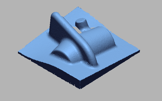
 Import 3D Scan File (5).png)
Import 3D Scan File
 Doing initial Allignment for alligning cad wit Scan data.png)
Doing initial Allignment for alligning CAD with Scan data
 Doing Best Fit Allignment for precise allignment.png)
Doing Best Fit Allignment for precise allignment
 Taking cross section.png)
Taking cross section
 Appling tolerance.png)
Appling tolerance
 Airfoil Measurements.png)
Airfoil Measurements
VIDEO
INDUSTRIES WE SERVE
WHAT'S NEXT?


RELATED BLOGS
Scan To Parametric CAD
Parametric cad consists of a history-based feature modeling tree that can be edited to make design
Read more
Scan To Parametric CAD
Parametric cad consists of a history-based feature modeling tree that can be edited to make design
Read more
Scan To Parametric CAD
Parametric cad consists of a history-based feature modeling tree that can be edited to make design
Read more