Overview
3D scan to 2D drawing inspection
Measuring parts throughout the manufacturing process is critical and has to meet specified tolerances. Traditionally, hand measurements with a variety of tools including calipers, gauges and fixtures are used to measure the part which is time-consuming and leads to human error. Mould and die casting industries or CNC lathe manufacturers often have 2D drawing or physical components with them. With the help of 3D scanning technology, we can initially capture the 3D scan data and import in the 3D inspection software like Geomagic Control X, where the scan data is compared to the nominal CAD model to evaluate both form and dimensional manufacturing details. Here 2D drawing is taken as reference data and 3D scan data of the object is taken first to make digital alignment to understand the part tolerances. Using the feature 2D measurement, the colour map, deviations and dimension interpretation is done on selected features. Geomagic Control X implements Geometric Dimensioning and Tolerancing to define allowable variations between nominal 3D geometry of the model and the 2D data. The 3D CAD file inspection report can be customized and given to the customer in the desirable format.
WORKFLOW
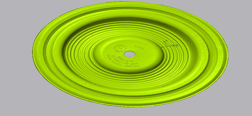
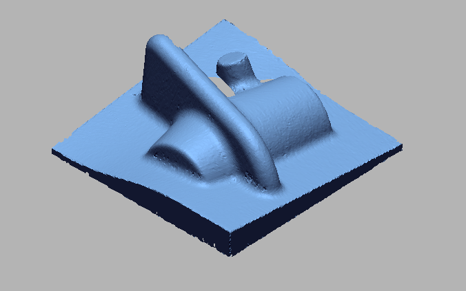
 Import 3D scan file.png)
Import 3D scan file
 creating plane for allignment.png)
Creating plane for allignment
 creating point for allignment.png)
Creating point for allignment
 creating vector for allignment.png)
Creating vector for allignment
 alligning 3d scan file as per 2d drawing.png)
Alligning 3D scan file as per 2D drawing
 now 3d scan file as per 2d drawing.png)
Now 3D scan file as per 2D drawing
 taking cross section for measurements.png)
Taking cross section for measurements
 change refernce as per 2d drawing.png)
Change refernce as per 2D drawings
 Measuring dimensions as per 2d drawing.png)
Measuring dimensions as per 2D drawing
 Final report comparison.png)
Final report comparison
IMAGE
VIDEO
INDUSTRIES WE SERVE
WHAT'S NEXT?


RELATED BLOGS
Scan To Parametric CAD
Parametric cad consists of a history-based feature modeling tree that can be edited to make design
Read more
Scan To Parametric CAD
Parametric cad consists of a history-based feature modeling tree that can be edited to make design
Read more
Scan To Parametric CAD
Parametric cad consists of a history-based feature modeling tree that can be edited to make design
Read more