Overview
Digital GD&T Analysis
Digital Geometric Dimensioning and Tolerancing (GD&T) analysis using 3D CT Scanning and 3D Laser Scanning to enable engineers to compare actual part metrology to desired dimensional specifications. The original CAD model was loaded and used as a reference to measure the deviation of the machined part. We use a 3D inspection software that has GD&T features to define the hole, slot, and surfaces from the design drawing. All of the GD&T features from the design drawing were measured right on the part in 3D. The color map confirms that the entire profile of the part meets the overall 3D profile tolerance established on the drawing. Our color map showed minor deviations in fillet radii, and machining marks left over from the CNC. We then conducted a full GD&T analysis using the 3D scan data as a reference. All of the features were measured automatically in 3D and we generated an inspection report detailing each feature and the deviation from nominal. Features that meet the criteria are highlighted in green.
WORKFLOW
 import Cad File (10).png)
Import CAD File
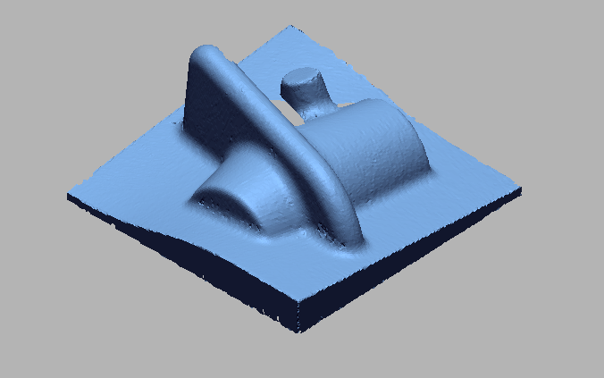
 Import 3D Scan File (12).png)
Import 3D Scan File
 Doing initial Allignment for alligning cad wit Scan data (2).png)
Doing initial Allignment for alligning CAD wit Scan data
 Doing Best Fit Allignment for precise allignment (2).png)
Doing Best Fit Allignment for precise allignment
 Digital GD_T Dimensions.png)
Digital GD_T Dimensions
 Digitial GD_T Dimension .png)
Digitial GD_T Dimension
 Digital GD_T Dimensions .png)
Digital GD_T Dimensions
 Digital GD_T Dimension1.png)
Digital GD_T Dimension

VIDEO
INDUSTRIES WE SERVE
WHAT'S NEXT?


RELATED BLOGS
Scan To Parametric CAD
Parametric cad consists of a history-based feature modeling tree that can be edited to make design
Read more
Scan To Parametric CAD
Parametric cad consists of a history-based feature modeling tree that can be edited to make design
Read more
Scan To Parametric CAD
Parametric cad consists of a history-based feature modeling tree that can be edited to make design
Read more