Overview
Parametric CAD
Before we talk about scan to parametric CAD, Let's explore what is parametric CAD and how they are typically made?
Parametric cad consists of a history-based feature modeling tree that can be edited to make design changes during any engineering design or product development. They are typically designed in CAD software such as CATIA, UG, Creo, Solidworks, by selecting an XYZ coordinate system reference plane. The user draws 2D sketches and then uses modeling features such as extrude revolve, sweep, etc.
3D Scan To Parametric CAD
is the reverse modeling process done in dedicated reverse engineering software, In which we import 3D Scan mesh as a reference and create a cross-section plane on the 3D mesh file in different angles and dimensions, using a reference cross-section profile we extract 2D sketch or draw 3D sketch directly on mesh file or use few more exclusive modeling technique to make the parametric model from the 3D Scan, the final design will be exported as CAD natural files for direct manufacturing, CAE and any other post design applications.
WORKFLOW
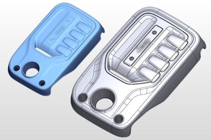
 Import Cad File (15).png)
Import CAD File
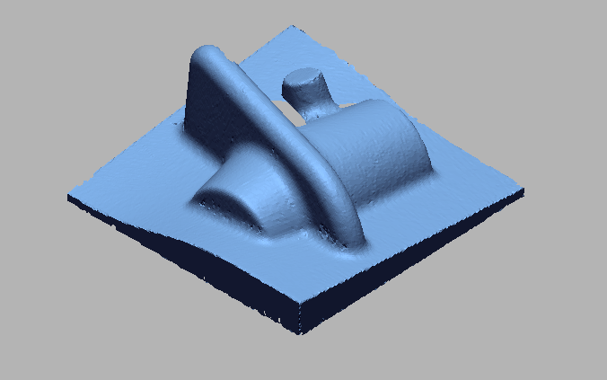
 Import 3D Scan Data.png)
Import 3D Scan Data
 Doing initial Allignment for alligning cad wit Scan data (3).png)
Doing initial Allignment for alligning CAD with Scan data
 Doing Best Fit Allignment for precise allignment (3).png)
Doing Best Fit Allignment for precise allignment
 3D Surface Comparison.png)
3D Surface Comparison
 2D Surface Comparison points.png)
2D Surface Comparison points
 Measuring 3D dimensions as per the drawing.png)
Measuring 3D dimensions as per the drawing
 Measuring 3D dimensions as per the drawing with tabular column.png)
Measuring 3D dimensions as per the drawing with tabular column
 2D dimesions takins as per the drawing.png)
2D dimesions takins as per the drawing
 Another Cross section for measuring 2d dimensions.png)
Another Cross section for measuring 2D dimensions
 2D dimensions with table.png)
2D dimensions with table
VIDEO
INDUSTRIES WE SERVE
WHAT'S NEXT?


RELATED BLOGS
Scan To Parametric CAD
Parametric cad consists of a history-based feature modeling tree that can be edited to make design
Read more
Scan To Parametric CAD
Parametric cad consists of a history-based feature modeling tree that can be edited to make design
Read more
Scan To Parametric CAD
Parametric cad consists of a history-based feature modeling tree that can be edited to make design
Read more